Getting Started
Update VTX Firmware
Please update VTX firmware to the latest version to ensure compatibility with the latest cameras, flight controller software, and video receivers. It is not required for VTX firmware version to match video receiver version, but it is recommended. See firmware update instructions below.
Caution: UFL Connectors Are Fragile
All HDZero VTXes use a U.FL connector for its smaller footprint and lighter weight. However, it is not a mechanically strong connector. Treat it as if it’s made of glass. Here are notes for installing and uninstalling an antenna:
Use the included brass or plastic retaining bar on VTXes that include it
If retaining bar is not used, never run a cable from the UFL connector straight off the side of a board. Instead, run the antenna cable towards the middle of the board, and secure it in one of the following ways as a strain relief:
Temperature resistant glue like E6000
Avoid using glue on top of the hot components on the board.
Preferably, apply glue to the side of the board where the cable leaves the top of the board.
Kapton tape to secure it to the surface of the VTX
Zip tie it to a nearby standoff (be careful not to crush the coax)
Unless you need maximum RF performance or minimum weight, consider a UFL->SMA pigtail for larger builds. This allows you to thoroughly secure the SMA connector to your aircraft to prevent movement of the antenna cable. Note: a common failure point with SMA connectors is where the coax cable is crimped to the SMA jack; if this joint snaps and is loose, RF performance will suffer greatly.
When removing the antenna, use care not to apply too much stress in any one direction. It is best to use a tweezer at the base of the neck of the connector and then pull straight up (do not pry), away from the board, so that force is evenly distributed on each supporting leg of the U.FL jack. There are tools designed to remove/insert UFL connectors from their sockets, which can help avoid damage to the UFL connector or socket.
Please visit the following link for more information:
https://www.facebook.com/groups/hdzero/permalink/448657693828864/
Powering the VTX: BEC
Using a battery eliminator circuit (BEC) is highly recommended to avoid voltage spikes, which can damage the VTX. Although you can power the VTX directly from the battery (VBAT), a BEC will provide more consistent power and will help absorb any voltage spikes, protecting your VTX from over-voltage conditions and under-voltage (brown-outs).
It is important to select a BEC that provides voltage that is within the range of what the VTX accepts, and that is capable of supplying enough current to power the VTX. Whether you are using a BEC that is built into your flight controller or a standalone BEC, be sure to check its voltage and current ratings and compare them to the required voltage and current for your VTX.
All the FCs that include an integrated BEC for DJI VTXes should also work for HDZero VTXes.
To summarize:
Check your FC specs to see if you can run your VTX from the FC’s BEC;
If not, you could run the VTX from a suitable standalone BEC;
If not, running on VBAT is always the last choice due to the challenging voltage environment in an aircraft.
All HDZero VTXes, except Freestyle V2, do not support 6S VBAT.
Mounting Considerations
It is very important to keep some distance between the VTX and ESC/FC boards for the following reasons:
The RF portion of VTX is vulnerable to electronic noise caused by ESC/motors;
The RF signal can be bounced back from surfaces of boards or carbon fiber plates, and fed back to the power amplifier in the VTX. This will deteriorate the RF signal integrity and could damage the amplifier.
To avoid these concerns, follow this guidance for mounting the VTX:
Do not use tape to mount VTX to drone frame (except for Freestyle V2)
If the VTX is mounted on the top of the stack, please keep 5mm distance from the top carbon fiber plates.
Avoid mounting the VTX in the middle of the stack.
If the VTX is mounted on the bottom of the stack, the VTX needs to be upside down (U.FL socket faces down) and needs to have a minimum of 5mm distance from the bottom carbon fiber plates.
OSD/MSP Setup
1. Pre-requisite
Betaflight >= 4.4.0
Inav >= 4.1
KISS ULTRA >= 2.0.1-B35
FlightOne >= 10.1.1.5576 | 10.1 Alpha 29
2. Update firmware VTX and VRX
Download the latest firmware: www.hd-zero.com/document
3. Solder/Connect VTX UART to an available UART on your FC board
See installation diagram above
4. Flight controller Configuration (Betaflight)
Connect the FC board to computer with a USB cable
Start Betaflight configurator
Go to Port TAB
Activate VTX (MSP + Displayport) on UART number that is used to connect the VTX
Save and Reboot
TIP
Note: A soft serial UART is not supported for VTX (MSP + Displayport).
As an example: UART5 on picture below is used for VTX (MSP + Displayport).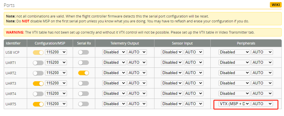
5. Restart/Connect Flight controller Configuration (Betaflight)
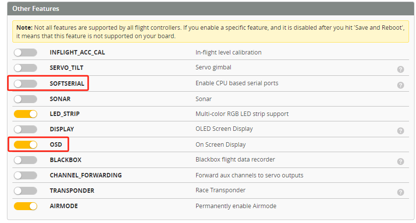
Go to configuration tab
Activate OSD function
SAVE
Go to OSD tab, and configure the items you want to show on your screen
SAVE
VTX Tables
The HDZero VTX tables have been integrated into the VTX firmware. It will automatically be configured if power on, which means you don’t need to configure it manually.
SmartAudio (Not Supported)
HDZero VTX does no longer supports SmartAudio. Use MSP OSD instead.
Stick Command Gestures
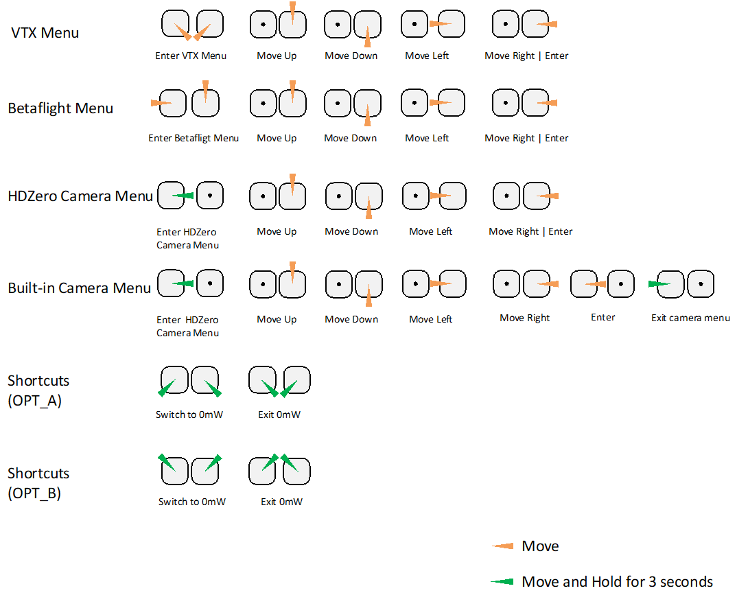
Using VTX Menu
All HDZero VTXes have the following settings for its RF power level management. These settings can be changed using the VTX menu.
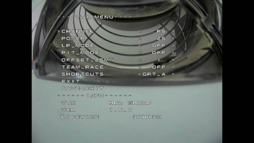
CHANNEL:
All VTXes support R1-R8, E1, F1, F2 and F4 channels. You will get an additional 8 channels L1-L8 if you unlock the low band.
POWER:
The desired RF power level is selectable between 25mW, 200mW (and 500mW or MAX for certain VTXes). The actual RF power level depends on the following settings and FC status.
PIT_MODE: (Set to ’OFF’ if you don’t know how it works)
OFF: The output RF power will be set to POWER setting.
P1MW: The output RF power will be 0.1mW (in order to not interfere with other pilots) in this mode. Exit using the VTX menu.
0MW: There will be zero RF output in this mode. Exit using the radio shortcut or via the VTX menu.
LP_MODE: (Set to ‘OFF’ if you don’t know how it works)
OFF: The output RF power will be set to POWER setting.
ON: If PIT_MODE is OFF and the aircraft is disarmed, the RF power level will be forced to 25mW regardless of POWER setting. The output RF power will be set to POWER setting when aircraft is armed.
1ST: If PIT_MODE is OFF, the RF power level will be forced to 25mW regardless of POWER setting when aircraft is power on, the output RF power will be set to POWER setting when aircraft is armed.
TIP
Note that after first arm, the vtx will not enter LP mode again until vbat power is reset
OFFSET_25MW: (Set to ‘0’ if you don’t know how it works)
It is to fine tune the RF output power to be exactly 25mW. The range is [-10:10], and step size is about 0.25dBm per step.
TEAM_RACE: (Set to ‘OFF’ if you don’t know how it works)
OFF: The RF power of VTXs after power-on is determined by other settings.
MODE1: VTX RF remains off (0mW) after power-up, and exits 0mW under the following conditions: 1. Exit 0mw mode through stick command. 2. Configure VTX power to non-0mW through FC UART. If the UART communication between VTX and FC is disconnected, VTX will turn off the RF until UART communication is restored and repower the VTX.
MODE2: VTX RF remains off (0mW) after power-up, and exits 0mW under the following conditions: 1. Exit 0mW mode through stick command. 2. Configure VTX power to non-0mW through FC.
SHORTCUTS:
Two different stick commands are provided for switching or exiting 0mW. See the Stick Movement diagram (OPT_A and OPT_B) for details.
TIP
Notes:
HDZero VTX will still become hot even on P1mW mode. It is better to keep VTX on 0mW when it will be idle for a while though the receiver will not have live video on this mode.
Use sticks shortcut to enter 0mW, and to exit 0mW mode.
Typical Setting for Racing or daily practicing
Channel: Set to the assigned number
Power: 25mW
PIT_MODE: OFF
LP_MODE: OFF
OFFSET_25MW: 0
TEAM_RACE: OFF
SHORTCUT: OPT_A
- When you are waiting for ARM command from race director, Use Stick Command (OPT-A / \) to enter into 0mW to avoid VTX overheats, no video in goggle
- Right before ARM command from director, use Stick Command (OPT-A \ /) to exit 0mW, you will have video in Goggle right away.
Typical Setting for Team Racing
Channel: Set to the assigned number
Power: 25mW
PIT_MODE: OFF
LP_MODE: OFF
OFFSET_25MW: 0
TEAM_RACE: MODE1
SHORTCUT: OPT_A
- When VTX boots up, it is on 0mW. It will start to transmit when using Stick Command (OPT-A \ /) to exit 0mW
- When you crash during the race, your VTX might continue transmitting, which will interference your teammate’s video signal that is on the same channel as yours, you need to
- Disarm, and use Stick Command (OPT-A / ) to enter into 0mW, this will work only when your FC still functions,
- VTX will automatically switch to 0mW after several seconds if VTX fails to communicate with FC (FC could be dead because of crash)
 Ligen
Ligen Eason FPV